Setting the scene
To show how it works, I went back to the POV-Ray ray-tracer I was fascinated by in the early 1990s. Przemysław Śliwiński of Wrocław University of Science and Technology gave me a head start, with the model behind his paper “A Simple Model for On-Sensor Phase-Detection Autofocusing Algorithm”.
Here’s our world, complete with a very 1990s wooden floor:
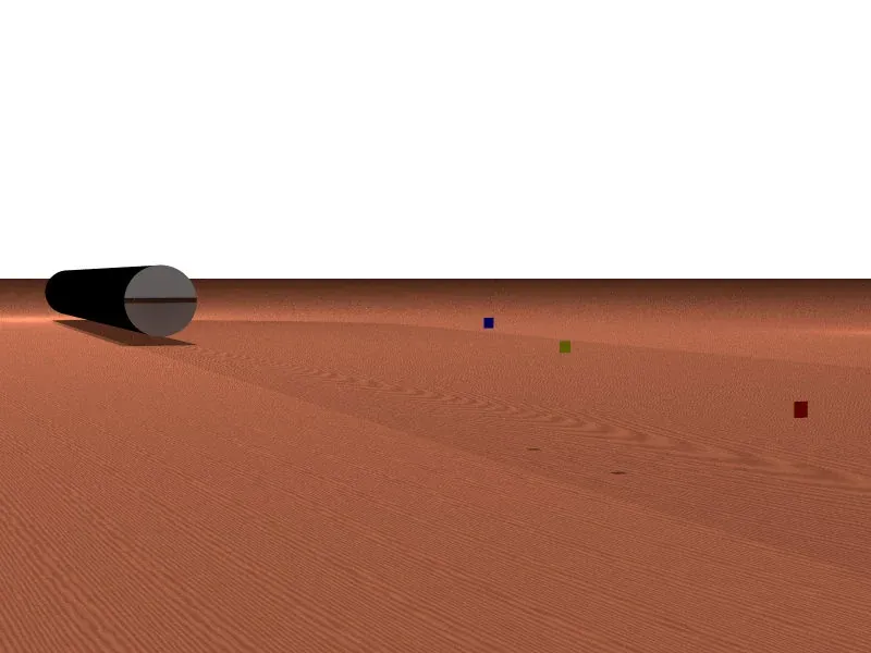
On the left is the “camera”. On the right are three targets, all the same size: blue nearest the camera, yellow in the middle, red furthest away.
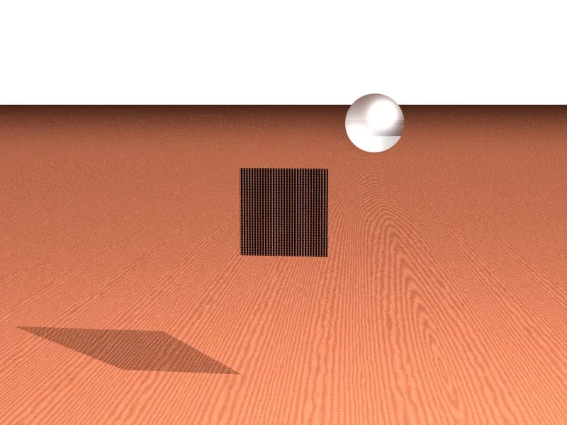
The camera has three parts: a lens at the front, a “sensor” at the back, and a tube to keep out stray light. Here it is from behind, without the tube, and then with it:
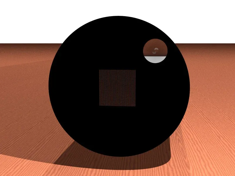
Take the sensor out and put your eye where it was, and this is what you see through the lens:
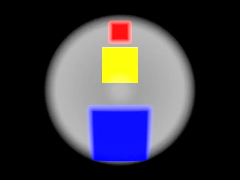
The lens puts the yellow target in focus at the sensor. The red one is further away and the blue one nearer, so both are blurred.
The sensor
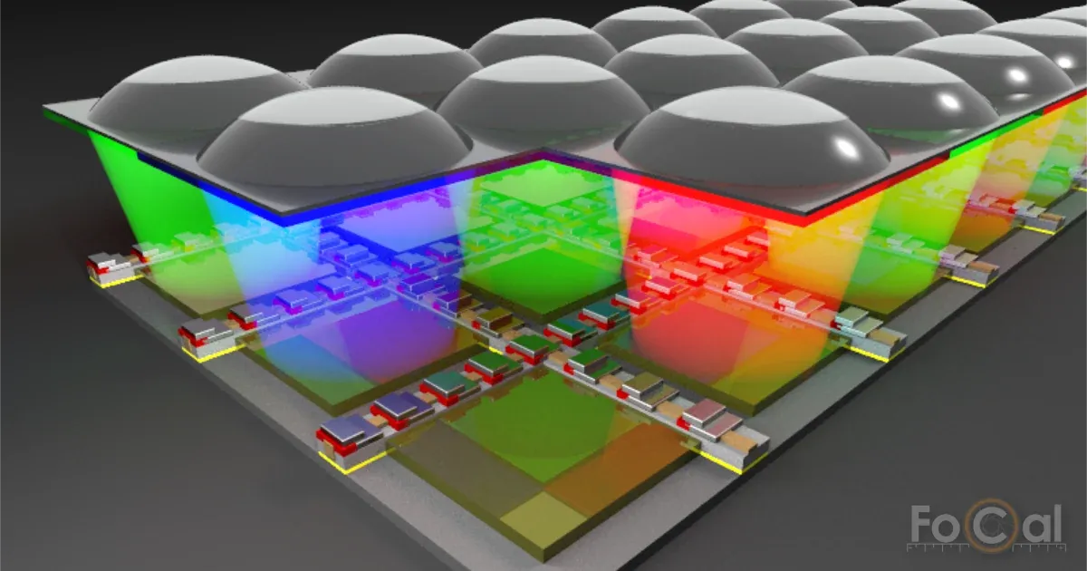
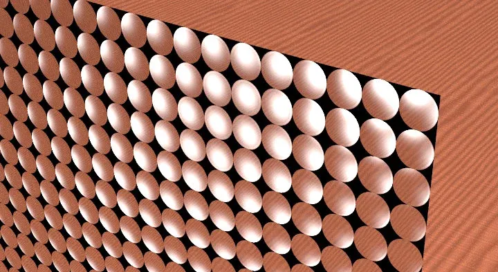
What I’ve called the sensor is an array of tiny lenses with a black mask between them. In a real camera, each of these microlenses sits over one light-sensitive photodiode (a pixel), usually with a colour filter in between, which doesn’t matter here.
Put that back in the camera and look through it, as the image sensor would:
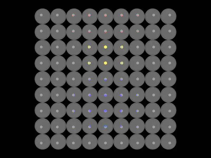
Not very impressive. But notice that each microlens shows a slightly different view of the targets, because the light reaching it takes a slightly different path through the main lens.
More lenses
Make the microlenses smaller and more numerous, and turn off the background light to make things clearer:
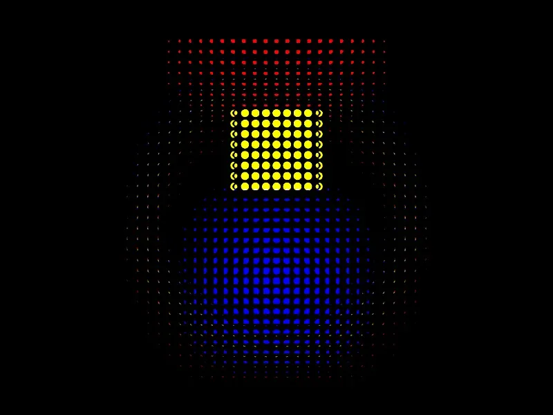
Now it gets interesting. (Ignore the faint yellow and red ring: it’s just light catching the edges of some lenses.)
The yellow target is in focus: you’re seeing it through lots of little circles, but it’s clearly a sharp square. The blue and red ones are out of focus, so their images spread out, turn rounder and cover more of the sensor. Just as you’d expect: shoot three squares with a wide aperture, focused on the middle one, and the other two blur towards circles.
Behind the mask
Now for the trick. Cover one side of each microlens with a dark mask:
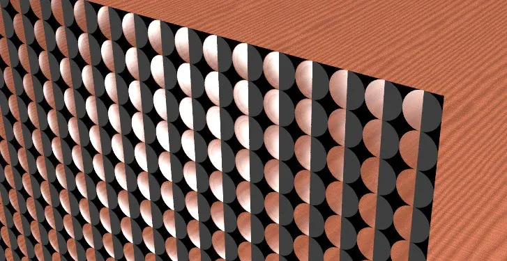
A small change, with a surprising result. Here’s the view with the left side of each lens masked, and then the right:
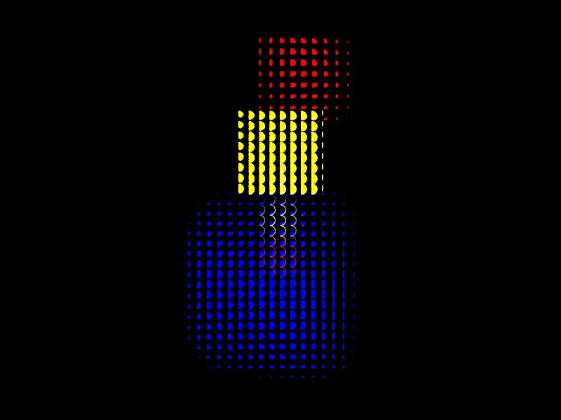
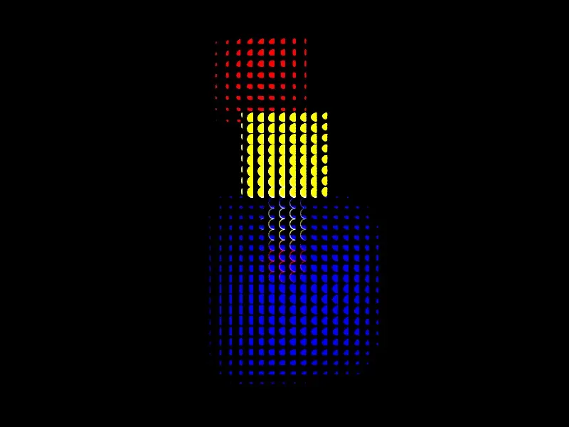
The red and blue images seem to have moved sideways, in opposite directions. They haven’t really moved: we’ve hidden part of each, so most of the light is now on one side of an imaginary centre line.
The in-focus yellow target looks the same through both masks. Masking makes only the out-of-focus parts of the picture appear to shift.
Shifting patterns
To see the shift clearly, here’s a single row of microlenses through each target. The two strips are the same part of the sensor: the top one through right-masked lenses, the bottom one through left-masked lenses.



Autofocus
So there’s an effect that depends on how far out of focus something is. How does a camera use it?
Below are the pairs of strips again, with a green reference line through the same point on the sensor in each. Slide the top strip until the two images line up, and the arrows show how far you had to slide it:
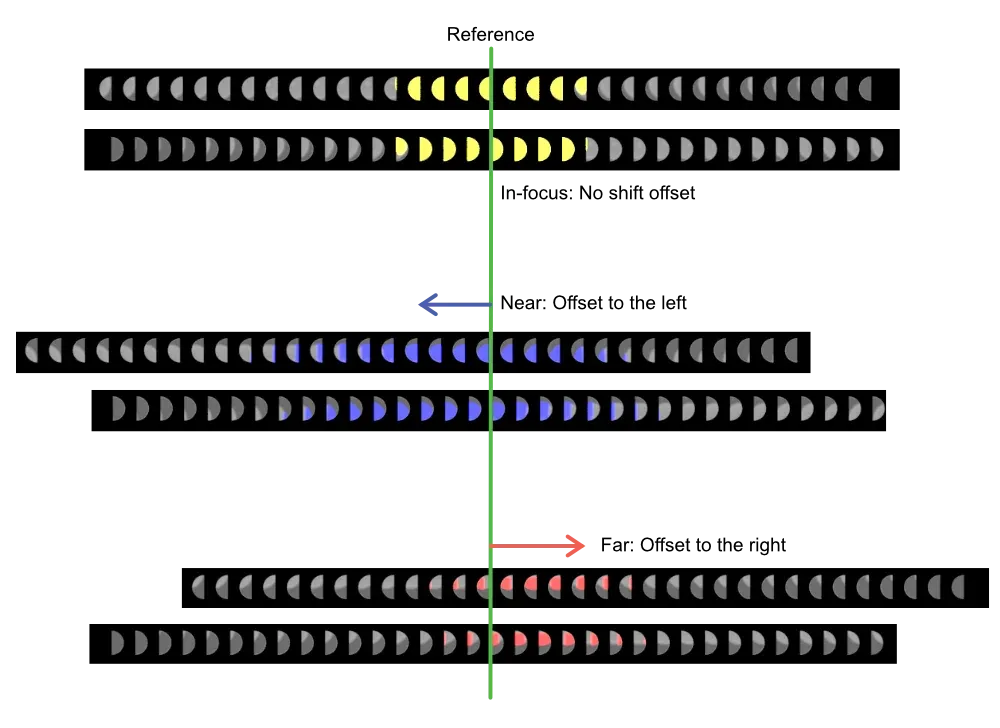
That gives two things for each target:
- how far it is from being in focus (the length of the arrow), and
- which way (the direction of the arrow).
From one exposure through masked microlenses, the camera knows how out of focus each part of the picture is, and whether it’s in front of or behind the point of focus. That’s the sensing half of phase detect autofocus.
In a real sensor
You can’t mask both sides of the same pixel, or nothing gets through. Instead, the sensor has pairs of special phase-detect pixels spread across it, one masked left and one right. They aren’t used for the picture, but they’re so small and spread out that the missing information disappears when the camera builds the colour image.
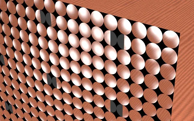
There’s another way: split each pixel into two side-by-side photodiodes that act as the left and right halves. That’s Canon’s Dual Pixel sensor, where every pixel is used for both autofocus and the picture.
And in a DSLR
On-sensor phase detect is what most mirrorless cameras use, and DSLRs too in live view. When you use a DSLR’s viewfinder, phase detect happens in a separate AF module, fed by a secondary mirror under the main mirror, because the mirror and shutter cover the image sensor until the shot is taken. Inside the module the idea is the same: light from two directions, and an offset between them that gives the amount and direction of focus. The DSLR guide covers why being separate matters so much.
On a mirrorless camera, focus is measured on the very sensor that takes the picture, which removes one big reason for calibrating. Next: why the measurement from those AF pixels still isn’t always perfect.